Recovering condensate from tracing lines
Steam tracing is used across various industries to heat products or raw materials to a specific temperature, to maintain their fluid state and enable pumping and distribution. Heating reduces viscosity and prevents crystallisation or solidification. Maintaining a uniform temperature of product / raw material across the entire length of the tracing networks is crucial to prevent choking which can hamper the process.
Steam tracers can be implemented in two ways: as a network of smaller pipelines running parallel to the process lines or as jackets surrounding the process lines, pipeline accessories, and pumps. Tracing systems are often intricate, with multiple individual tracers for each process line. Each tracer line itself needs to have an individual trap at the tracer termination point, along with isolation valves to isolate steam to the tracer, as well as isolation valves before and after the trap to facilitate trap maintenance. If the process line extends beyond the tracer termination point, a new tracer is used to continue the tracing.
Across several plants condensate is not recovered from steam tracing networks. Recovery from tracers is a challenge primarily due to design constraints. However, through a properly designed steam tracing network with steam and condensate manifolds, the plant can simplify the piping network, eliminating a complex maze of piping. Steam manifolds enable centralised distribution of steam to multiple tracers, while condensate manifolds serve as central collection points for condensate from multiple tracers. These manifolds incorporate valves, allowing for isolation of steam or condensate for each individual tracer. This setup facilitates safe and easy operations and maintenance for each individual tracer. The illustration below demonstrates the significant impact that correct design can have on operational efficiency and maintenance of the steam tracing system.
Illustration of a plant showing a conventional fabricated condensate manifold for tracing network vs forged condensate manifold for tracing networks
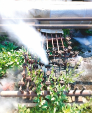
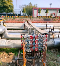
Before After
Illustration of a plant showing a conventional fabricated condensate manifold for tracing network vs forged condensate manifold for tracing networks
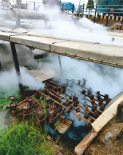
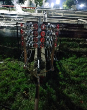
Before After
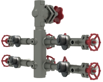
Forged Manifold with Thermostatic Steam Trap for Tracing Applications
When steam flows through the tracers, it releases its heat to the surface. The heat energy is transferred to the process pipeline, raising the temperature of the process fluid. Besides latent heat, sensible heat can also be utilised in steam tracing to provide heat to maintain the desired temperature.
Thermostatic steam traps are best suited to effectively manage condensate in steam tracing networks. These traps incorporate a thermostatic capsule that holds back the condensate and allows it to be discharged only when it cools down to a specific temperature. This mechanism ensures that besides latent heat, some portion of sensible heat is also used for tracing.
