Where can Flash Steam be used
Using flash steam within the process in a low pressure (LP) application
When it is not possible to recover flash steam to the boiler feed water tank, prioritising its use within the process becomes important. This can occur in the following scenarios:
- The plant relies on purchased steam and does not generate steam in-house.
- The distance between the flash steam generation source and the boiler feed water tank is significant, and there is a high possibility that the flash steam will condense before reaching the feed water tank.
- The feed water tank which is operating at atmospheric pressure, already has excess heat recovery, and the plant does not wish to convert it into a pressurised deaerator.
In these situations, it becomes more advantageous and practical to utilise the flash steam locally within the process area. Flash steam recovery to the process may also be considered if the flash generation source is in close proximity to its point of use, thereby reducing the quantum of piping and its associated costs.
The feasibility of using flash steam locally within the process depends on several factors, such as availability of a suitable low pressure application, the proximity between the flash steam source and the process application, and considerations related to the overall system design.
The go-to chart below can help you evaluate whether it makes sense to recover flash steam to the process.

Go-to chart – utilise flash steam in the boiler feed water tank or locally in a process
Each application should be carefully evaluated to ensure that the local utilisation of flash steam is technically and economically viable, while still meeting the process requirements effectively.
Illustration:
The following example demonstrates how the recovery of flash steam in an instant noodle manufacturing plant has a significant impact. In this process, the noodle cakes are steamed using live steam and then flash fried. The total heat requirement is 23.4 Million Kilocalories/hour, with 9.4 Million Kilocalories/Hour going to the steamer and 14 Million Kilocalories/Hour going to the fryer. A steam boiler provides this heat to both the processes. While the steamer receives direct steam injection, the fryer uses a heat exchanger to heat the frying oil (indirect steam consumption).

Example of recovering flash steam to a low pressure process application (before)
While the plant was recovering condensate, flash steam was being vented to the atmosphere. As the steamer was a low pressure steam consumer, flash steam could easily be utilised there.

Example of recovering flash steam to a low pressure process application (after)
By recovering the flash steam, the plant was able to reduce the steamer’s consumption of live steam by 17%, from 9.4 to 7.8 Million Kilocalories/Hour. In terms of steam, this reduction was approximately 2.9 Tons/Hour or about 19,550 Tons/Year.
Additionally, because the flash steam was previously vented into the atmosphere, an equivalent amount of fresh makeup water had to be added to the boiler. However, with the recovery of flash steam, there was a simultaneous reduction in fresh water consumption by 19,550 Kilolitres/Year.
Look for uses which can be converted to LP
Across plants there are several equipment which operate at pressures higher than necessary. For example equipment where process temperature requirements are below 100oC are often supplied steam at 3-3.5barg.
Such equipment can be evaluated for operation at lower pressures where flash steam can be utilised.
Boost flash pressure using thermocompression and use it in a medium pressure (MP) application
In some cases, low pressure applications may not be available in the plant. However, even in such situations, it is still possible to recover flash steam to the process by boosting its pressure. This can be achieved by using a thermocompressor system.

Thermocompressor
The thermocompressor is a device that utilises high pressure motive steam to entrain and compress low pressure suction steam including flash steam, boosting its pressure and making it usable in applications that require a higher pressure. The thermocompressor comprises a motive nozzle, a suction chamber and a diffuser. The high pressure motive steam is expanded through the nozzle. The pressure head of the motive steam is converted into velocity head by the nozzle and the low pressure steam is entrained by this high velocity.
The velocity head of the mixture (discharge steam) is reconverted to pressure head by the diffuser (refer to the illustration).
To determine if it is feasible to boost flash steam pressure and use it in an application the following parameters need to be considered:
- The intended process application for steam usage should have a consistent and uninterrupted steam.
- The steam consumption of the process should be higher than the sum total of the suction steam (flash steam) and the motive steam required.
- To be able to boost the pressure of flash steam to the desired level for use in the process application, it is necessary that motive steam is available at a pressure greater than twice the required discharge pressure (in absolute units).
- The ratio of the discharge pressure to suction pressure should be less than 2.5 (in absolute units).
- The ratio of the motive pressure to suction pressure should be greater than 2.5 (in absolute units).
- The entrainment ratio, which is the ratio of the flow rate of motive steam to the flow rate of suction steam should be less than 4.
Illustration:
Take the example below in a plant with two steam consumers, A, which consumes 900kilograms/hour steam at 5barg and B which consumes 500kilograms/hour steam at 2barg.

Boosting flash steam pressure for use in the process
Both processes put together will generate 103kilograms/hour of flash steam @ 0.5barg.
M b (Steam consumption in B) = 500kg/hr b
M S(Suction steam flow rate) = 103kg/hr s
P S(Suction pressure) = 1.5 bar a (0.5barg) s
P d(Discharge pressure) = 3 bar a (2barg) d
Entrainment ratio = 3.5
The required motive pressure P m can be determined by the following equation:
equation
Pm ≥ Pd
x 2.66 = 3 x 2.66 = 7.98 bar a
Therefore the motive steam pressure should be greater than or equal to 7.98 bar a or 6.98barg
The motive steam quantity (Mm) can be determined by the following equation
Therefore the motive steam quantity (Mm) = 362kg/hour
M (Discharge flow rate) = M + M = 362 + 103 = 465kg/hr
To determine the feasibility of thermocompressing this flash steam and utilising it in
equipment B, it needs to satisfy the following conditions.
- M b (500kg/hr) > 465kg/hr i.e. Ms (103kg/hr) + Mm (362kg/hr)
- To be able to boost the pressure of flash steam to the desired level for use in the process application, it is necessary that motive steam (Pm) is available at a pressure greater than 2xP. 2xP =6 and motive steam is available at 11bar a
- The ratio of the discharge pressure to suction pressure should be less than 2.5 (in absolute units) Pa/P3<2.5 i.e. 3/1.5 = 2<2.5
- The ratio of the motive pressure to suction pressure should be greater than 2.5 (in absolute units) P_/P3>2.5 i.e. 7.9/1.5=5.26>2.5
Since it satisfies all conditions it is feasible to thermocompress the flash steam from A and B and utilise the same in equipment B. This will reduce the steam requirement of equipment B by 103kg/hr.
Recover flash steam to the boiler feed water tank
Flash steam can also be reclaimed back to the boiler feed water tank. However, when recovering flash steam to the boiler feed water tank, two considerations should be taken into account. Firstly, if the boiler feed water tank operates at atmospheric pressure, the addition of flash steam should not raise its temperature beyond 90°C as this will result in boiling in the feed tank leading to significant vibrations and
possible damage to the tank as well as heat loss from the tank. Second, it is important to ensure that the distance between the flash steam generation source and the boiler feed water tank is not excessive, as this could cause the flash steam to condense before reaching the feed water tank. Flash steam to the feed water tank should always be routed through a deaerator head to enable proper mixing of flash,
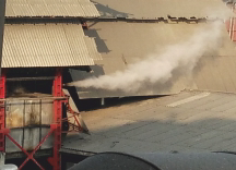
condensate and make up water. In the absence of a deaerator, flash steam will not completely quench and will partially vent out of the tank as seen in the illustration below.

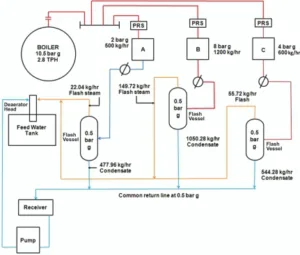
A typical schematic for recovery of flash steam to the boiler feed water tank is illustrated below.

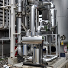
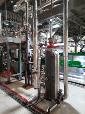
Figure 24: Flash steam and condensate recovery to the boiler feed water tank (Actual plant images)


